

Troubleshooting Common Faults in HV Lightning Impulse Voltage Generator Systems
Even well-maintained HV Lightning Impulse Voltage Generator Test Systems develop faults over time. Components age, connections loosen, insulating oil degrades, and measurement chains drift. The ability to diagnose and correct these faults quickly distinguishes a high-availability laboratory from one plagued by repeated test failures and inconclusive results. This article presents a systematic troubleshooting framework for the most common problems encountered in impulse generator operation, organized by symptom rather than by component, since operators typically observe abnormal waveforms before identifying the underlying cause.
Waveform distortion is the most frequent symptom and the most diagnostically informative. If the impulse front time is longer than the specified 1.2 microseconds, the cause usually lies in excessive circuit inductance or insufficient generator energy. Long connecting leads, loosely routed conductors, or a poorly designed test circuit layout add inductance that slows the voltage rise. Replacing round cables with coaxial or strip conductors and shortening lead lengths often restores the correct front time. When front time elongation appears suddenly after a period of normal operation, a loose high-voltage connection or a partially failed front resistor should be suspected. Thermal imaging of connections during charging can reveal hot spots indicative of increased resistance.
Tail time deviations point to different root causes. A tail time shorter than 50 microseconds suggests that the tail resistance has decreased, possibly due to resistor overheating or moisture ingress. A tail time longer than specified indicates increased tail resistance or a change in load capacitance, such as an additional test object connected in parallel. Overshoot exceeding the 10 percent limit typically results from excessive circuit inductance combined with insufficient damping. In such cases, increasing the front resistance or adding a damping resistor near the test object can suppress oscillation. However, any adjustment to wave-shaping components must be followed by full waveform verification, since front and tail times interact and correcting one parameter may disturb another.
Spark gap instability manifests as erratic firing, inconsistent output voltage, or complete failure to trigger. Electrode erosion is the leading cause, as each discharge vaporizes a small amount of electrode material and gradually increases the gap distance. When the gap grows beyond the design value, the breakdown voltage rises and may exceed the charging supply's capability, causing misfires. Recalibrating gap spacing to the manufacturer's specification, typically using precision feeler gauges, restores reliable operation. Contaminated electrodes, caused by oil vapor or dust deposition, also impair triggering; cleaning with fine abrasive paper and solvent followed by gap readjustment resolves this condition. Trigger electrodes and their associated pulse transformers should be tested for continuity and insulation integrity, as a weak trigger pulse produces intermittent firing that mimics gap problems.
Capacitor degradation develops slowly and is easily overlooked until waveform quality deteriorates noticeably. Oil-filled film capacitors lose capacitance as dielectric layers absorb moisture or experience partial discharges. A capacitance bridge measurement of each stage, compared against the original factory values, reveals drift beyond the typical two percent tolerance. Insulation resistance testing with a megohmmeter detects moisture ingress, with readings below 1000 megohms indicating the need for oil processing or capacitor replacement. Visible bulging, oil weeping from bushings, or discoloration of the capacitor case are definitive signs for immediate replacement. Since capacitors are typically configured in series within each stage, a single degraded unit affects the entire stage output and can unbalance voltage distribution, accelerating aging of neighboring capacitors.
Measurement errors often masquerade as generator faults, leading technicians to adjust the generator when the actual problem lies in the instrumentation. A voltage divider with degraded resistors produces a scale factor error that shifts the apparent peak voltage without any change in actual generator output. Step response testing of the divider, performed at least annually, detects such drift. Low-resistance or damped-capacitive dividers are particularly susceptible to damage from flashover across their high-voltage resistor elements. Impulse analyzers with outdated firmware may apply incorrect evaluation algorithms, producing erroneous front and tail times from valid waveforms. Updating software and verifying the analyzer against a calibrated signal generator eliminates this class of error.
Grounding and interference problems produce symptoms that are difficult to reproduce and diagnose. Inadequate grounding causes waveform noise, baseline drift, and occasional spurious triggering. Measuring ground grid resistance and verifying that all components connect to a single reference point eliminates circulating currents. Electromagnetic interference from nearby equipment, particularly during charging, couples into measurement cables and corrupts low-voltage signals. Shielded cables with proper termination, physical separation between power and signal routing, and ferrite chokes on sensitive lines reduce interference to acceptable levels. When troubleshooting proves inconclusive, comparing current waveforms against the commissioning baseline file, shot by shot and parameter by parameter, is the most reliable method for isolating the true cause. Systematic documentation of every fault, its diagnosis, and its remedy builds institutional knowledge that shortens future repairs and protects test quality.
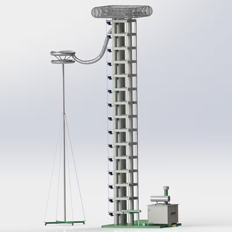 Impulse Voltage Testing of Power Transformers Using HV Lightning Impulse Generator Systems
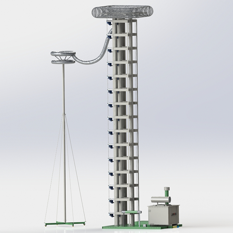 Troubleshooting Common Faults in HV Lightning Impulse Voltage Generator Systems
 Digital Integration and Remote Monitoring of DC High-Voltage Generators in Industry 4.0
Automating Insulating Oil Dielectric Loss Testing: A Guide for High-Volume Laboratories and Utility Fleets
Digital Integration and Remote Monitoring of DC High-Voltage Generators in Industry 4.0
Automating Insulating Oil Dielectric Loss Testing: A Guide for High-Volume Laboratories and Utility Fleets