

Impulse Voltage Testing of Power Transformers Using HV Lightning Impulse Generator Systems
Power transformers represent the single most valuable asset in most transmission and distribution networks, and their insulation systems must withstand the transient overvoltages produced by lightning strikes and switching operations. The HV Lightning Impulse Voltage Generator Test System is the primary instrument for verifying this capability. Transformer impulse testing is among the most demanding applications of impulse generation, requiring precise waveform control, high energy delivery into strongly capacitive and inductive loads, and careful interpretation of diagnostic signals. This article examines the test procedures, practical challenges, and evaluation techniques specific to transformer impulse testing.
The governing standard for transformer impulse testing is IEC 60076-3, which defines test levels, sequences, and acceptance criteria according to the transformer's highest voltage for equipment. Standard lightning impulse tests use the 1.2/50 microsecond waveform, while switching impulse tests, required for transformers rated at 300 kV and above, use the 250/2500 microsecond waveform. The test sequence typically begins with a reduced-level impulse at 50 to 75 percent of the specified withstand voltage, followed by three full-level impulses of both positive and negative polarity. The reduced-level shot serves as a reference, establishing the baseline response of the winding before full stress is applied and permitting comparison of subsequent waveforms.
Full-wave testing reveals the transformer's ability to withstand the peak voltage without insulation breakdown. The generator must deliver sufficient energy to maintain the specified waveform despite the transformer's winding capacitance, which can reach several nanofarads for large units, and its inductance, which affects the impulse tail. Waveform parameters are measured at the reduced-level shot and verified to fall within IEC tolerances before proceeding to full level. If the front time at full level deviates from the reduced-level value, the generator's energy storage or the test circuit configuration requires adjustment. Experienced engineers recognize that the transformer itself forms part of the test circuit, and its frequency-dependent behavior influences the measured waveform at the bushing terminal.
Chopped-wave testing adds a critical dimension to transformer verification. In this procedure, the impulse is deliberately chopped by a triggered spark gap after a specified delay, typically between 3 and 6 microseconds, simulating the effect of a surge arrester operating or a flashover occurring near the transformer terminals. IEC 60076-3 requires that the chopped-wave peak exceed the full-wave peak, and that the voltage collapse to zero within a specified time without excessive opposite-polarity overswing. The transformer experiences its most severe dielectric stress during chopped-wave testing because the rapid voltage collapse drives steep-fronted waves into the winding, exciting inter-turn and inter-coil insulation. A generator with reliable chopping gap control and precise timing circuitry is essential for this test.
Diagnostic evaluation extends beyond simple pass or fail criteria. Transfer function analysis, performed by comparing the reduced-level and full-level waveforms in the frequency domain, detects changes in winding geometry that indicate insulation displacement or turn-to-turn faults. Any deviation between the reference and subsequent waveforms, whether in amplitude, oscillation pattern, or high-frequency content, warrants investigation. Modern digital recorders capture waveforms at sampling rates exceeding 10 megasamples per second, enabling detailed spectral comparison. Some laboratories also monitor partial discharge activity during impulse application, providing additional evidence of insulation weakness that may not be visible in the voltage waveform alone.
Practical challenges in transformer impulse testing frequently arise from the interaction between generator and load. Large transformers present a predominantly capacitive load at the impulse front and a complex impedance during the tail, causing waveform distortion if the generator's output impedance is not well matched. The test circuit layout, including the length and routing of high-voltage leads between generator, divider, and transformer bushing, introduces inductance that affects front time. Laboratories often construct a dedicated test bay with short, low-inductance connections and a fixed generator position to minimize shot-to-shot variability. Ambient conditions, particularly humidity, influence flashover behavior across bushing surfaces and must be monitored and recorded.
Acceptance criteria require that no insulation failure occurs during the test sequence and that the waveform parameters remain within tolerance. A transformer that passes the full-wave test but exhibits waveform distortion during chopped-wave testing may still be acceptable if the deviation is attributable to normal circuit behavior rather than insulation fault. Conversely, a minor change in transfer function, even without visible waveform abnormality, can indicate a serious internal defect. Interpretation therefore demands experienced engineering judgment supported by comprehensive documentation. Following a successful test, the transformer is considered verified for lightning impulse withstand, and the recorded waveforms become part of its permanent test record, available for future comparison should the unit require re-testing after repair or relocation.
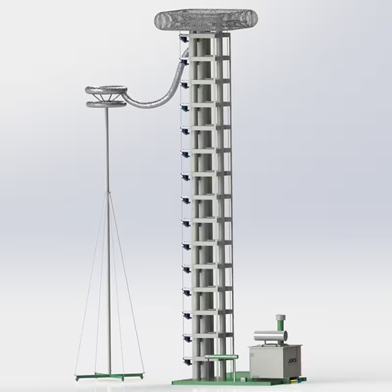 Impulse Voltage Testing of Power Transformers Using HV Lightning Impulse Generator Systems
 Troubleshooting Common Faults in HV Lightning Impulse Voltage Generator Systems
 Digital Integration and Remote Monitoring of DC High-Voltage Generators in Industry 4.0
Automating Insulating Oil Dielectric Loss Testing: A Guide for High-Volume Laboratories and Utility Fleets
Digital Integration and Remote Monitoring of DC High-Voltage Generators in Industry 4.0
Automating Insulating Oil Dielectric Loss Testing: A Guide for High-Volume Laboratories and Utility Fleets